COMPONENTS
Introduction
A component is an instance of a device, picked from one of the device libraries. Since some devices are multi-element it follows that in some cases, several components on the schematic may, in fact, all belong to one physical component on the PCB. In such cases, the logical components are annotated with names such as U1:A, U1:B, U1:C, U1:D to indicate that they all belong to the same physical part. This form of annotation also enables Proteus to select the correct set of pin numbers for each element.
Apart from physical terminals, components are the only objects you can place which will generate physical entities in the PCB design. Everything else you place serves either to specify connectivity, or else is present only for the purpose of human readability. This is an important point, since attempts to use other schematic objects (in particular, graphics symbols) to represent objects on the PCB will fail.
Selecting Components from the Device Libraries
When you start on an empty drawing, the device selector is empty. Before you can place any components, you must first pick them from the libraries into the selector.
To select components from the device libraries:
- Select the component icon from the Mode Selector toolbar.
- Click left on the 'P' Button on the Object Selector. This will cause the Device Library Browser to appear as shown below.

- Either enter one or more keywords or else navigate through the category and subcategory columns to filter down the indexing system and locate the desired library part.
- Double click on a part in the results list in order to select it into the design.
- When you have finished picking devices, use the ok button to close the dialogue and return to the schematic.
See Also:
Picking Parts from the Library (Tutorial)
Placing Components
Component placement follows the general scheme outlined in Object Placement.
To place a component:
- If the device type you want is not listed in the Object Selector, first select component mode and then pick it from the libraries as described in the previous section.
- Highlight the device name in the Object Selector. Proteus will show a preview of the device in the Overview Window.
- Use the Rotation and Mirror icons to orient the device according to how you want to place it.
- Click left in the Editing Window to enter placement mode. At this point a shadow outline of the component will appear.
- Move the mouse to the point at which you want to place the component and left click again to commit and exit placement mode.
Replacing Components
To replace a component:
- Proceed up to stage four in the steps for placing a component. You should now have a shadow component following the mouse.
- Move the shadow component over the existing component such that at least one of the pins is exactly over a pin on the existing component and the mouse itself is over the existing component.
- Click left to replace the component on the schematic with the one you are currently placing.
You can also replace a component by using the Property Assignment Tool with the syntax 'DEVICE=<component_name>' in on-click mode. This may of course result in chaos if the part is wired.
Editing Components
A component may be edited using any of the general editing techniques (see Editing an Object). To edit the component under the mouse, right click on it and choose Edit Properties, or use the keyboard shortcut for that command (by default CTRL+E), or double left click on it in selection mode. To reach a component by its reference instead, use the Find/Edit Component command on the Edit menu (default keyboard shortcut key 'E'), which searches the design for the reference you type, jumps to the sheet it is on and then opens its dialogue form.
As with most editing features in Proteus a dialogue form will appear with the appropriate editing fields. However, with the Edit Component dialogue form the available fields are dependent on the given properties of the component. You will find, therefore, that this dialogue form can be radically different for different components. Context Sensitive Help is available for the dialogue form but please note that, for the reasons given above, some fields may not have a help topic associated with them.
See Also:
Having said that, several specific attributes are common to components and can be found at the bottom of the dialogue form. Three in particular are used to exclude the component from various other modules and are discussed below:
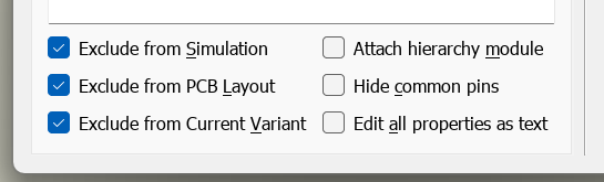
The three exclusion checkboxes on the Edit Component dialogue form
Exclude from Simulation
When checked the component will not be included for simulation purposes. This should be used for example with connectors which have no meaning in a simulation but are relevant in PCB layout.
Exclude from PCB Layout
When checked the component will not be included for PCB layout purposes. Obvious examples include virtual instruments (e.g. oscilloscope) which is relevant for simulation but clearly not for layout.
Exclude from Current Variant
When checked the component is marked as not fitted in the assembly variant that is currently selected, which is what removes it from that variant's Bill of Materials. This is useful where you want a single board fabricated that might satisfy scalable product. For example, a lower cost product might not include bluetooth connectivity but would still use the same mainboard as the more expensive variant.
The checkbox is a shortcut for a single part. Assembly variants themselves are created, named and switched between from the Assembly Variants system, which is the place to start if you are setting up a product range. The checkbox is disabled while the base variant is current, since nothing can be excluded from the base.
See Assembly Variants for the full picture.
Attach hierarchy module
Also on the dialogue form, this checkbox turns an ordinary component into the parent of a child sheet, which is the route into hierarchical design from a part you have already placed. See Hierarchical Designs.
Gate-Swapping Components
The Edit Component dialogue form also enables gate-swap and re-annotation of multi-element parts. A multi-element part is a single physical part with several contributing logical elements. The common database deals primarily with parts and it is therefore not possible for elements to supply conflicting data. This is most obviously seen with properties; unlike earlier versions, changing a property in one element will automatically change that property in all of the other elements of the part.
The annotation and swapping of gates in the Edit Component dialogue now works slightly differently. Take the following as an example:
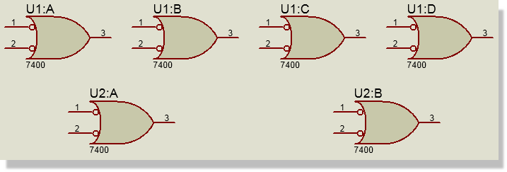
The four elements of a multi-element device annotated U1:A to U1:D
When placed, an element reflects both its part reference (e.g. U1) and its element identifier (e.g. A). In the Edit Component dialogue these are separated into two fields.
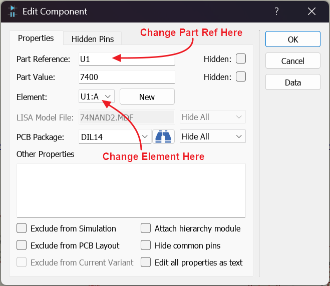
The Part Reference and Element fields on the Edit Component dialogue form
Part Reference
Changing the part reference will re-annotate all of the elements. For example, changing U1 to U4 will change all of the U1 elements to U4 elements. You will get a warning if you change this annotation to one that is already in use (for example U2).
Element
Changing the element will swap the current element with the one selected from the combo box. Pressing the new button will change the annotation to the next available element not currently on the schematic.
Examples
To re-annotate U1 to U4
Edit one of the U1 elements and change the part reference to U4

All four U1 elements re-annotated to U4 after the part reference is changed
To gateswap U4:A with U4:C
Edit the U4:A element and change the element to U4:C.

U4:A and U4:C exchanged by the gate swap
To annotate a heterogeneous part
If you have a multi-element heterogeneous part such as a relay with a coil and contacts the process is similar to that in previous versions. When you place the elements on the schematic they will be un-annotated as manual annotation is required for heterogeneous parts.
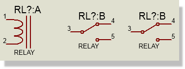
The coil and contacts of a relay placed but not yet annotated
The annotation of each element is of the form
<part ref> : <element>
and is entered in the part reference field of the dialogue. For example, the coil might be annotated as RL1:A and the contacts as RL1:B and RL1:C
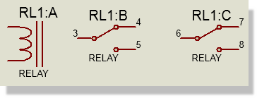
The same relay annotated RL1:A for the coil and RL1:B and RL1:C for the contacts
Assuming the contacts are identical, you can subsequently gateswap them via the element field of the Edit Component dialogue.
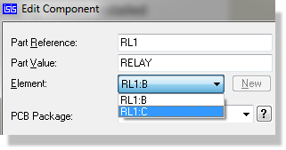
Swapping two identical relay contacts with the Element field
The gateswap will only work if the contacts are instances of the same library part. Since they are identical, you need only one library part, regardless of how many contacts are placed on the schematic.
Component Properties
Components have the following system properties:
| Property Name | Description |
|
REF |
Component Reference designator label. |
|
VAL |
Component value label. |
|
VALUE |
Component value label or the VALUE user property if the assigned text is too long for the label. |
|
DEVICE |
Library part. If assigned, this will invoke the automatic replacement logic which will attempt to maintain connectivity. |
If any other property names (e.g. RoHS, TOLERANCE, etc.) are assigned, then these will create user properties in the component's text block.
The manufacturer and stock code held in the device library are also offered for editing on the dialogue form, as MFR and STOCKCODE. If you leave either at the value the library part supplies, it is not stored against the component, so the part is not flagged as locally edited and the library value continues to follow through when the device is replaced.
Where the component comes from a managed library, its properties are maintained by the library and the option to edit them as free text is not offered.
See Also:
Bill of Materials (Properties)
Visual Packaging Tool (Properties)
Hidden Power Pins
If a component has been defined with hidden power pins, then the nets to which these will be connected can be viewed or edited by switching to the Hidden Pins tab of the Edit Component dialogue form as shown below. The tab provides eight fields, so a component can have its hidden pins directed to up to eight named nets.
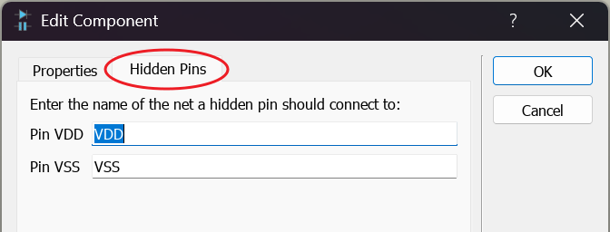
The Hidden Pins tab of the Edit Component dialogue form
By default, hidden pins connect to a net of the same name. A hidden VDD pin will connect to VDD, a hidden VSS pin to VSS and so on.
See Also: